astrorat.com
SBC6120RBC (PDP8/e) Project
Digital PDP8/e Minicomputer

Back during my collage days, one of the computers I used during computer lab was a Digital PDP8/e connected to a Digital DECWriter III. I have many fond memories of powering up, loading paper tape load program via the front panel switches, then loading the boot loader from paper tape and finally booting into OS8. Our lab assignments were mostly programming in BASIC and sometimes Fortran IV.


Over the years I have been looking for a PDP-8e to restore and add to my collection of vintage hardware. During a Vintage Computer Festival Mid-West (VCFMW) back in 2017, I ran into an atheist selling a new version of PDP8/e kit called the SBC6120RBC Edition.


The SBC6120RBC Edition used the Harris HD-6120 CMOS “PDP-8 on a chip”. The HD-6120 is a general-purpose high speed, CMOS 12-bit microprocessor designed to recognize the instruction set of the Digital Equipment Corporation's PDP8/e minicomputer.


This version of kit was a follow on based on the original SBC6120 designed by Robert (Bob) Armstrong of Spare Time Gizmos from 2002 to 2011. Sometime after Spare Time Gizmos stopped selling boards and kits, Bob garishly released the design into the GNU Free Documentation License, Version 1.1.


he RetroBrew Computer (RBC) Community took the original board layout and re-implemented it into KiCAD as a 2-layer PCB.  The resulting board was the SBC6120RBC Edition.
The SBC6120 was basically a more modern version of the original PDP8/e. During the original rollout, a FP6120 front panel was developed by Bob. With the FP6120 plugged into the SBC6120 you ended up having a PDP8/e look and feel. Unfortunately, unlike the SBC6120, the FP6120 front panel was not picked up as a re-implementation by the community.
Original Spare Time Gizmos SBC6120
The FP6120 Front Panel
Spare Time Gizmos FP6120

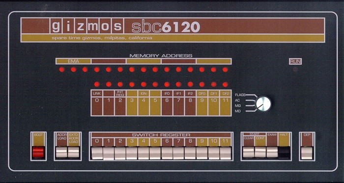
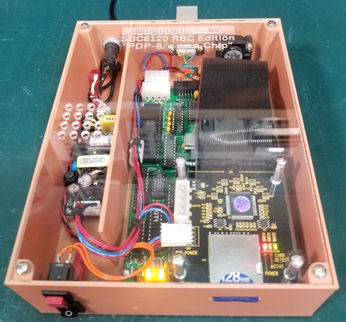
I really wanted to have the FP6120 for my SBC6120RBC system. Unfortunately, the front panel has been out of production for years. Like the RBC community, I re-implemented the front panel also in KiCAD as the FP6120DTR and ordered some PC boards for my SBC6120 system.


My re-implementation follows the original electrical design very closely. I also tried to scale several pictures and drawings to re-create a physical layout which closely matches the original front panel. I did exclude the I/O expansion board, compact flash card and IDE disk drive mounting locations for my re-implementation.


Once I removed the extra mounting locations, I realized the switching power supply, power switch and supporting 9-volt DC connecter could also be excluded. All the required power need would be received via the 50-pin interface connecter on the SBC6120 main board.


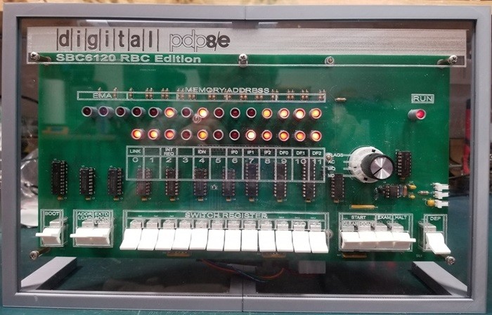
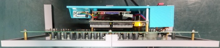
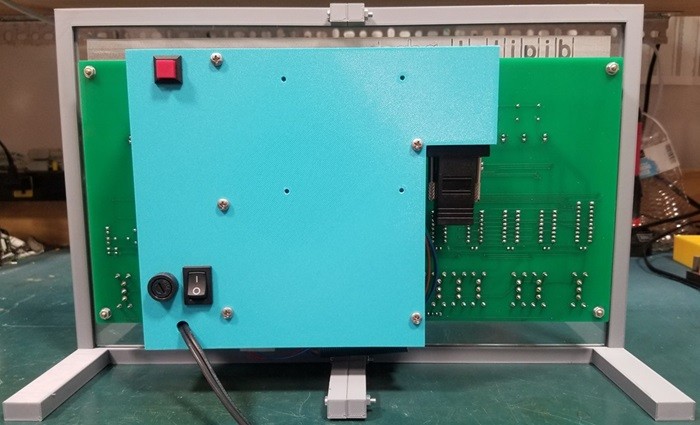
Some of the mechanic changes made was excluding of the LED BAR on the front of the board assembly. I opted instead created 3D printed LED parts that provide both spacing and light isolation. Finally, I moved the board mounting holes. I place five mounting holes around the outside edge of the PC board.


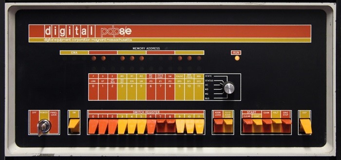
One thing I still have not been able to recreate is the nice front panel artwork that mimicked the look and feel of the original PDP-8e. In the end I used my LASER cutter/etcher to create a see through acrylic front panel which nicely shows of the under workings of the front panel.


This is the link to the PDF for the FP6120DTR version front panel schematic.

This is the link to the PDF for the FP6120DTR version front panel BOM.

SBC6120RBC with FP6120DTR
SBC6120RBC Edition with FP6120DTR

Like it's predecessor, my version also supported a mostly traditional PDP8/e style programmer’s console to any SBC6120 system. With twenty-seven LEDs providing continuous display of current memory address, memory or register contents, and an additional LED to display the running or halted state of the processor.


Twelve data switches for direct entry of binary data and eight switches providing program control functions including BOOT, ADDRESS LOAD, EXTENDED ADDRESS LOAD, CLEAR, CONTINUE, EXAMINE, DEPOSIT and HALT.


Given that front panel allows the mounting of the SBC6120RBC board on the back, a simple 3D printed enclosure was created. This enclosure supports the mounting of a 128MB SD card assembly that acts as the hard drive storage, the main switching power supply and a DB9 serial connector. There is also a power switch and reset button.

Mounted SBC6120RBC, FP6120DTRTop-Down View
SBC6120 Back Side View
In the end I ended up crating two SBC6120RBC Edition systems. The First is a unit which includes a front panel seem above which I keep in my retro computer display area. The second is a system is identical to the first but missing a front panel.  This system is also enclosed in a 3D printed box with a LASER cut/etched clear acrylic cover and is in the engineering lab area.
SBC6120 without a Front Panel
Updated - 10/2/2024