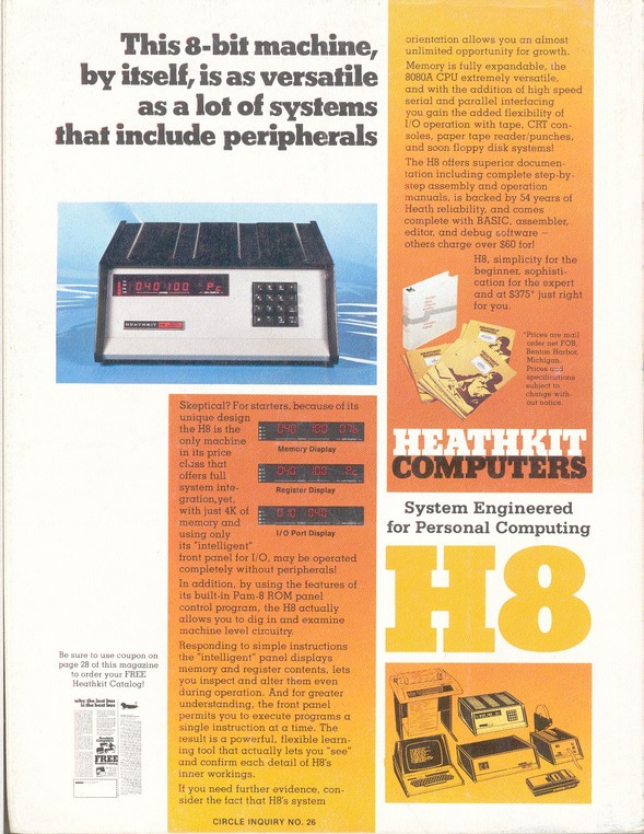
A little bit about the Heathkit H8
Heathkit had always been know for its useful and quality electronics kits. Dating back to 1926, they first offered a light airplane in kit form, moving to war surplus components in the 30's, and eventually to more modern audio and electronics test equipment, small projects, and HAM radio communications systems. Releases in late 1977, the H8 was the first computer system made available from Heathkit. While other computer manufactures were producing some computer systems in kit form, the practice was quickly fading from th market. Heathkit continued to produce computer kits thought the companies final years of operation.
| Announced: |
July 1977 |
| Available: |
Fall 1977 |
| Original price: |
$379 (0K RAM) |
| CPU: |
Intel 8080A @ 2MHz |
| Interface: |
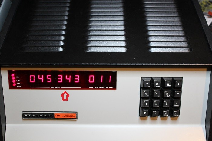
16-button keypad
9-digit Octel LED display |
| Storage: |
Optional audio cassette
Optional Floppy drive |
| OS: |
Heath DOS (HDOS)
CP/M (Therd party offering) |
The engeners at Heath chose not to implement the popular S-100 bus fond in many units of the day. They instead created "Benton Harbor Bus" named after their home town. Their bus was based on a 50-pin connecter type already be used in other Heathkit projects. Design consideration in the bus laid out, helped avoid some of the common electrical problems of the MITS S-100 system. For example having +5V and ground being placed beside each other.
The H8 design was packaged in a chassis using pressboard on the sides and sheetmetal for the rest of the case. There is no fan in the H8. Cooling is provided through the heavily perforation of top and bottom sheetmetel covers forming cooling vents. These vents allow cool air to flow from bottom, thorugh the installed boards and the hot air exits out the top.
When the H8 was introduced, the computer market was moving from the hobby market to a "user" market that wished to purchase pre-assembled systems. The Heath company followed this trend by introducing is own prewired vertion known as the WH8. The base unit cost started from $475 with 0K of RAM.
|
Source: Vintage Computer Museum Service - West Falls, NY
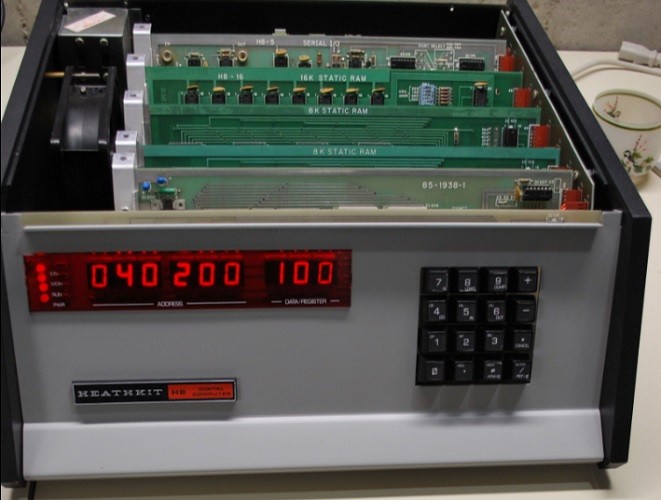
The following five picture where supplied to show to condition and installed optional boards supplied as part of the H8 system being offered for sale. While the pictures seem to show the unit to be in an overall good condition, there was no guarantee that it would be fully operational. There would most likely be some surprises once I received the system in my lab where I could do a complete review.
While I was waiting for the system to be shipped to my location, I used the supplied pictures to begin the process of researching and collecting documentation needed for the restoration process.
| Discription |
Model |
Serial # |
| Main Computer System |
H8 |
04825 |
| 8K Static RAM Board |
H8-3 |
02839 |
| 8K Static RAM Board |
H8-3 |
02839 |
| Audio cassette and Serial Board |
H8-5 |
05825 |
| 16K Static RAM Board |
Hw8-16 |
38340 |
|
 |
| Front View |
|
|
 |
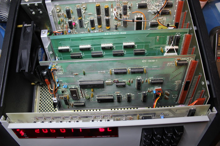
| Wide Indside View |
|
|
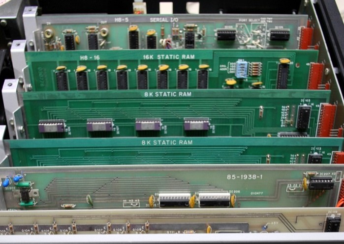 |
| Closer Inside View |
|
|
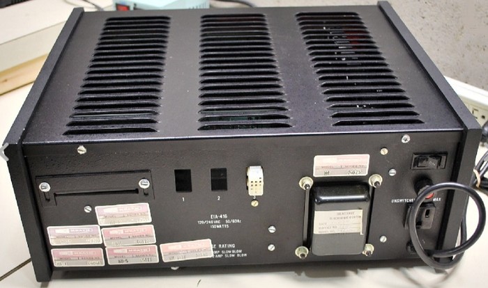 |
| Backside View |
|
|
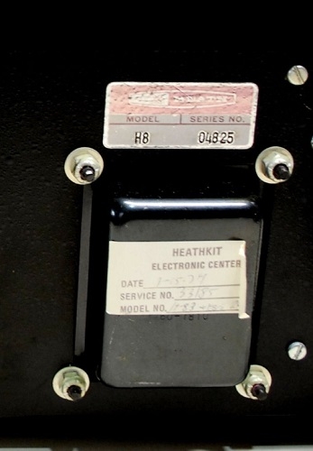 |
| Closeup of Serial Number |
|
|
The H8 Restoration Begins
So the H8 did not work out of the box...no surprise!
The unit was shipped to me in a box that protected the H8 from the many horrors found in shipping these days. It was indeed in good physical condition just as the pictures indicated.
But the H8 did not power up correctly.
This really did not really surprise me in the least. The seller was up front about not being able to verify that the system fully worked. The pictures showed the unit powered up but when I applied power, I got nothing. I knew this was sold as an as-is purchase and I am prepared to fix any issues that are found.
|
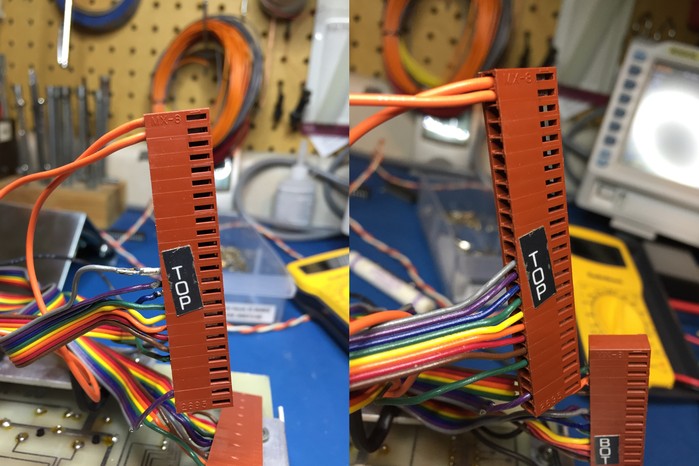
The problem that stopped the system form working.
Look at the left side in the above two pictures. Can you see the issues on the connector labeled "TOP"?
It
turned out the main issue keeping the H8 from starting up properly, was
bad pin crimps. The "TOP" connector makes up one of two connectors
that plug in to the H8's back plane at location P1. Both the "TOP" and
"BOT" connectors create the interconnection between the H8 front panel
and the system back plane. A review of these connectors showed a total
of five pins with poor to bad crimps. One was physically damaged in some
way. Three of these pins are clearly visible in the left above picture.
My
decision was to remove and cut off all of the crimped pins for both
connectors. Then each wire was re-crimp using my lab's professional
crimping tools. I also changed from the basic tin pins originally
supplied with the kit, to gold plated ones while I was at it. The
resulting repaired "TOP" connector is shown in the right hand picture.
With
this repair in place, the H8 again sprang to life with all supplied
board seemed to be fully functional. The ease of the repair surprised
me. I planed on doing a lot more major reiteration work.
|
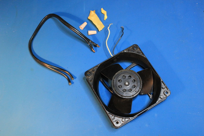
The big noisy fan has to go
Adding a cooling fan to an H8 was a popular user upgrade. To help keep the cost down, Heathkit attempted to design a passive cooling arrangement in to the H8. Many verbalization slots in the case cover and many holes in the bottom would allow cool air to flow from the bottom through the system's boards and the warm air would exit out the top. In theory keeping the system within safe operating parameters.
Unfortunately, this cooling system design did not always work as planned. My last year working at my Heathkit store, I worked as a repair technician fixing all types of user induced problems. I saw many H8s come over my bench that where assembled correctly but with burned out voltage regulators or in some cases 8080 processors. It is my opinion that these system where running too hot.
Like many others, at some point the original owner installed a fan. A big, noisy, 120Vac, 120x120x38mm, 135CFM fan to help keep the system cool.
It is safe to say the system indeed ran cool!
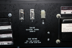
Another issue I had was the 120Vac cable that connected the fan to the main power switch on the back of the system used some form of cheep, 18AWG, zip-type extension cord. Two wire-nuts and some "masking tape" was used to connect the zip-cord to the fan's wiring. Also to accommodate the fan's power needs, the main system fuse was increased from the rated 1-amp slow-blow to a 5-amp one. To bad the other supporting ac wiring did not support this larger current draw.
Really the selected fan was overkill form what is really needed and the supporting wiring had to go!
Given there was already a 120x120mm hole pattern drilled in the left hand case side, any replacement fan really needed to use the same form factor as the old fan. I selected a nice ball bearing fan that measured 120x120x25mm, moved 70CFM@29db(A) and runs using 10VDC@250mA. A wiring harness with an in-line fuse was created to connect the fan directly to the H8's main power capacitor.
The main system power fuse was replaced with the correct 1-amp version.
The resulting cooling generated by the now quiet fan still keeps all the system's cards running well within their safe operation ranges.
|
Huston we have a problem!
Okay so I spoke too soon. There was a hard to find issue with the 32K of static RAM that came with the system.
I did do several hours of memory testing on each of the three supplicated memory cards looking for any memory issues. In this original testing nothing became apparent.
The issue that would take me hours to locate became apparent one day while I was loading and working with the H8's Benton Harbor BASIC interpreter. It first showed up when I loaded version 10.6.0 from tape. Every time I created a short BASIC program and then tried to list it out, all the line numbers would be in decimal form. So line 10 turned in to 0.14267 in a list.
When I then loaded version 10.5.1 of the BASIC, everything seemed to work. So is the tape image of the 10.6.0 I'm using corrupted? I starting to use the 10.5.1 version.
Everything seemed to work with the 10.5.1 with the exception that every once and a while the BASIC would just lockup for no reason. There seemed to be no patterns in these lockups that I could discern. Could the 10.5.1 have some type a memory leak or other coding issue?
Over time the lockup issue started to get on my nerves. Then one day when the system located up again, I did not power the system down but instead entered in and then ran the simple RAM test program that came from the Heathkit H8 operations manual.
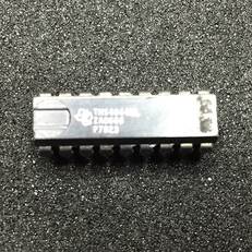
BINGO! The test program found that a small bock of locations, in the upper 4K bank, on one of the two 8K SRAM cards had stuck bits in the high state. Moreover the issues would come and go intermittently. Further more this issue took time to appear after the computer was powered up from a cold state.
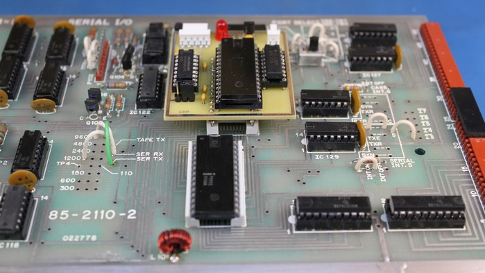
The picture above shows the offending TSM4044 SRAM chip that was located in IC108 on the H8-3 card.
I replaced all eight of the TMS4044 chips with newer and factory fresh P2141 version I already have in my restoration parts stock. Plugging in the repaired board, several different memory test programs for where run over two days.
Now all version of BASIC 10.6.0 and 10.5.1 work. All the BASIC programs that I have been porting over are also now working. No more lockups.
So everything seems to now be working again??? Lets hope so!
|
Adding two standard DB9 connectors
The classic H8 computer featured three rectangular holes label 1
through 3 on the back side of the unit. These three holes where there
to support the additions of Molex 15-pin connectors. It was through
these Molex connectors that you connected your H8 to serial peripherals
like the H9 terminal or the H14 dot-matrix printer.
While
these connectors where functional, they where not conferment to the
normal standard DB25 or later the smaller DB9 connectors in use for
RS232 based serial communications.
To
make my H8 easier to interface to all the DB style cabling I already
had in place for all my other retro computer systems, I opted to
slightly modify two of the three holes labeled 1 and 2. To mount a
standard DB9 connector in to one of these rectangular holes, two shallow
half-moon shaped slots needed to be filed in to the case.
While
I hate making a physical change like filing slots in to my vintage H8, I
felt the end results of standardizing my serial cabling justified that
modification. If I wished to use the original Molex 15-pin connectors, I
could with the connectors covering most of the modification.
With
this modification in place, I can now connect my terminal to DB9
connector labeled 1 and use the second DB9 labeled 2 for transferring
H8T formatted files between my laptop and the H8.
|
Adding a RS232 Interface to the H8-5 Cassette Interface
The H8 system I received came with the H8-5 cassette/serial interface card. While I tested the cassette interface using one of the lab cassette recorders to write and then read back a tape, it became clear to me that finding working 35+ year old tapes for the H8 would be some what of a challenge. Even if I locate anything, the age of these tapes would most likely reveal that any data stored on them to be quite dicey to read back. Another solution would need to be developed.
|
The first attempt...
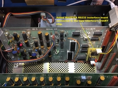
For my first attempt, the solution came in some form of a card being added to the H8-5 card. This extra card creates a standard RS232 interface between the H8-5's tape interface circuit and a PC.
As it tuned out, I already had such a card designed for one of my other projects. This card had two 5-pin connectors for power plus TTL/CMOS signals and another for the RS232 interface.
The picture above shows the modification. Also note the standard DB9 connector that returns to my lab's PC where I read/write H8T program files.
As mentioned earlier this board came form another of my projects. Over time I have been designing and restoring computers based around the RCA 1802 microprocessor used in the COSMAC Elf articles in 1976 and 1977. One of the more resent Elf's designs I has acquired was the Membership Card by Lee Hart.
I ended up designing an interface card to both power and provided RS232 interfacing for my Membership card. Using this card as a starting point I updated it to be used as the first generation interface board to connect the H8-5's tape electronics to an RS232 serial connection ending at one of my PCs.
In the original Member Card version, I had a DC power connector that ran to an on board analog +5 volt DC regulator circuit. Since I was going to pull +5 volt DC straight from the H8-5 card, I had no need for the parts used in this portion of the circuit. I just left the parts off the board leaving empty holes.
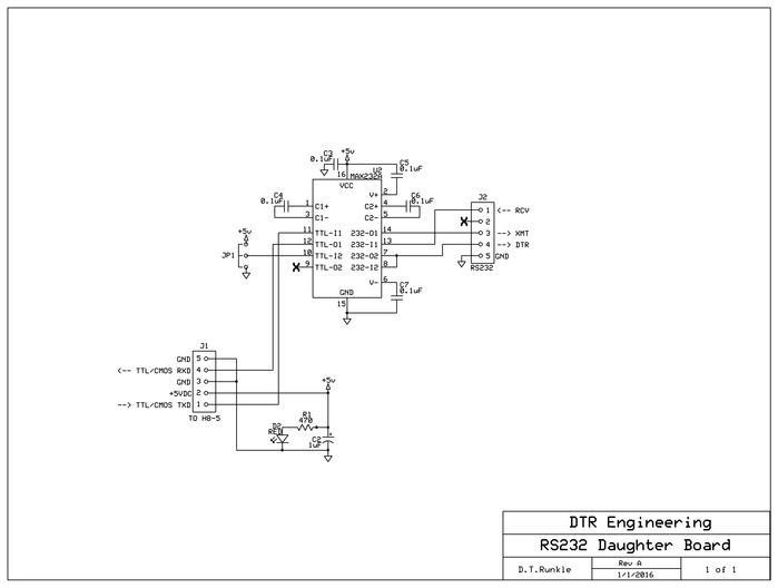
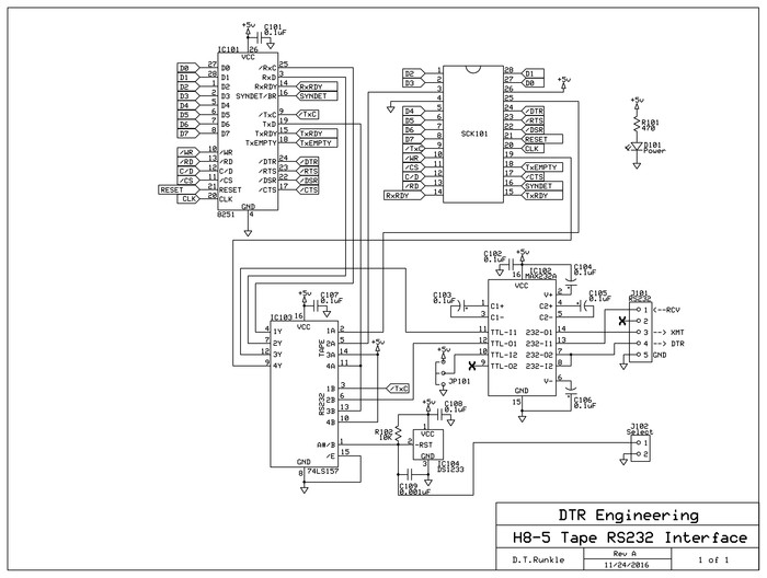
The following schematic show the resulting daughter board design.
It tuned out the unused large mounting hole normally used by the analog 5 volt regulator could now be re-used as a board mounting hole to mount the daughter board to an unused hold already on the H8-5 card. I only needed to place a threaded 4-40 x 1/2 inch nylon hex spacer between each of these two holes.
Wiring to the daughter board uses four 24AWG wires that are routed to solder points on the H8-5 card. These wire routes connect the +5V(red wire), ground(black wire), TxD signal(Gray wire) and RxD signal(orange wire). The solder locations used made sure that no foil on the H8-5 board needed to be cut.
|
To complete this modification several IC pins had to be disconnected and one IC had to be removed. These modifications are needed to prevent interference between the daughter board and the original tape interface electronics.
To disconnect an IC's pin, simply remove the IC from it's socket, carefully bend the needed pin very slightly out and finally re-install the IC back in to the socket making sure the pin to be disconnect does not go back in to the sockets hole. When done correctly the disconnected pin should just be on the outside of the IC socket.
The following list shows the removed IC and the disconnect pins needed:
Remove IC107
Disconnect IC112 pin 1
Disconnect IC108 pin 6
Disconnect IC117 pin 8
The final operation needed to complete this modification is placing a shorting jumper between pins 9 and 25 on IC123. This jumper is placed on the back side of the H8-5 board and hence is not visible in any of the pictures.
This jumper is needed to connect the received data clock (pin 25) to the baud rate clock already being used by the transmit data clock (pin 9).
The down side of this modification is the disabling of the tape interface itself. If we wished to use a tape recorder to save or load programs, we would have to reinstall the disconnected pins, reinstall the removed IC, remove the jumper on the back of the board and unplug the daughter board cable used to connect it to the H8-5.
|
The daughter board - a better solution for transferring H8T files between H8-5 Board and a PC
Click here to get the full PDF manual for the H8-5-1 Daughter Board projectMy first attempt to in creating an RS232 serial interface used to transfer files between my H8 and a standard PC, used an existing board from one of my other projects. While this board did successfully create an interface, it required the removal of several integrated circuits on the H8-5 board. It also required the soldering of extra wires. This rendered the native cassette tape interface non-operational. For me, this was unsatisfactory. Some form of interface system was need that allowed the H8-5 to be fully functional in both modes of operation. Tape interface and RS232 serial. After reviewing the H8-5's schematic, the idea of creating a plugable daughter board seemed logical. This daughter board would replace the P8251 UASRT at location IC123.
The resulting design is shown in the picture above. Operation of the H8-5-1 Daughter Board is very simple. A sign SPST switch is used to select between normal Cassette Tape operation or using an external RS232 serial connection to a PC other serial data device. When the two pins on J102 are shorted the Tape mode is selected. Leaving the input on J102 open places the system in to serial transfer mode. The red LED indicates the board is receiving +5 volt DC power. The three pin jumper at JP101 may be used to generate a high or low RS232 signal output level at pin 4 of J101. This signal can then be used to place any handshake lines on an external serial data storage device into a required state Refering to the sechamitc below for a circuit description. IC102, C102 through C106, JP101 and J101 make up the RS232 serial interface circuit. The core of the interface is the MAX232A (IC102) integrated circuit. RS232 level signals are routed through the 5-pin connector J101 to the MAX232A. Here the RS232 signal levels are converted to standard TLL or CMOS digital levels. The four 0.1uF capacitors C103 through C106 are used by the MAX232A to create both a 5 volt to 10 volt voltage pump as well as a –10 volt inverter. While the pump/inverted combination can only source/sink a few milliamps, this is more than enough to handle most standard RS232 interfaces found on terminals or PCs. Selectable jumper JP101 may be used to set up a RS232 high or low logic level on pin 4 of J101. This optional signal may be used to define a needed handshake inputs that might be needed while interfacing external serial device. The final 0.1uF capacitor C102 is a simple power rail decoupling capacitor for IC102. IC103 and C103 make up the serial signal switching circuit. Serial signal switching is handled by a 74LS157 (IC103) quad 2 to 1 data selector integrated circuit. Serial data to and from the P8251 (IC101) along with the serial input clock are switched between ether the normal cassette interface electronics or the RS232 serial interface section handled by the MAX232 (IC102) described above. Integrated circuit DS1233 (IC104), 10K ohm resistor R102 and a 0.001uF capacitors (C109) are used to create a switch debounce used by the incoming switching single received via 2-pin connector J102. This 3-pin, TO-92 cased integrated circuit is also used as a power on reset controller for the board. When power is applied, the DS1233 monitors the VCC supply until it reaches about 10% of 5 volts. When VCC returns to an in-tolerance condition, the reset signal continues the active low state for approximately 350ms to allow the power supply to stabilize. The 10K resistor R102 is used to pull high the switch input while 0.001uF capacitor C109 is used to help stabilize the switch debounce function on the DS1233. While the input to J102 is in the open state, the resulting control signal into the 74LS157 (IC103) pin 1 will be high selecting the external RS232 signaling. Shorting pins 1 and 2 on J102 will pull the DS1233 low placing 74LS157 (IC103) pin 1 low and selecting the normal internal cassette tape interface. Removing the short on J102 again allow the DS1233 to return the select signal to high after a pre-programmed debounce of 350mS. The final 0.1uF capacitor C108 is a simple power rail decoupling capacitor for IC104. The remaining IC101 socket is the P8251 integrated circuit removed from the original H8-5 circuit board and place on to the daughter board. For the circuit description of this component, refer to the Heathkit documentation supplied with the H8-5 board.
|
Using RealTerm to load H8T files
The following are the steps I use to transfer files from my laptop or PC to my H8 computer's H8-5 card using the H8-5 daughter interface board shown above.
|
STEP 1 - If not already done so, Power up the H8 computer.
|
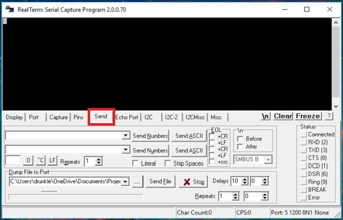
STEP 2 - On the source PC where you have all your H8T files loaded, startup the RealTerm program and select the Send tab.
|
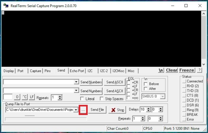
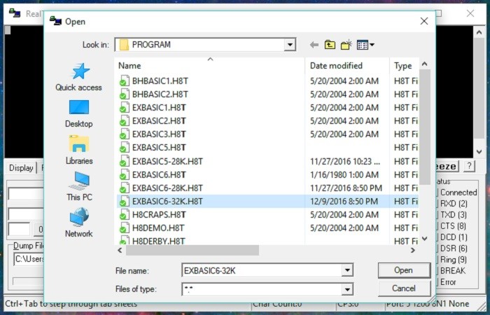
STEP 3 - Now we need to find the H8T file we wish to send. Open the files list by clicking on the indicated button.
|
STEP 4 - The Open dialog window should open listing the contents of the current folder. Navigate to the location of your H8T files you wish to send. Then select the file you wish to send and click on the Open button.
|
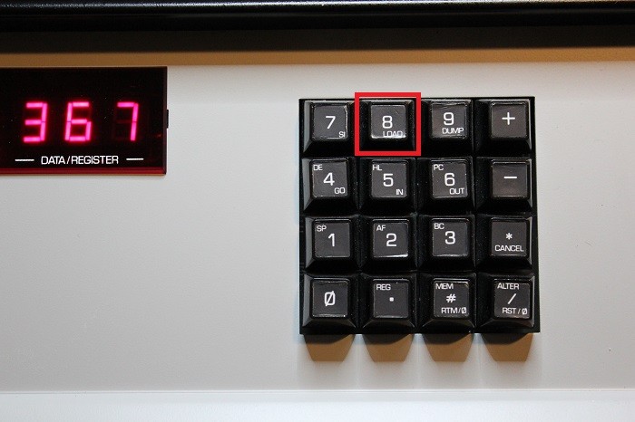
STEP 5 - Now we setup the H8 to receive the sent file. Press the indicated "Load" button.
|
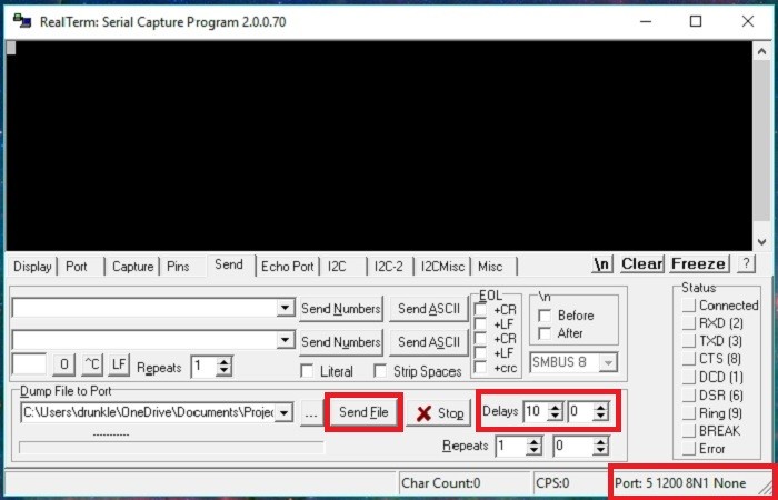
STEP 6 - Before we click on the Send button, verify that the serial port's speed is set to the correct baud rate for your setup. The normal default for an H8-5 Cassette/Serial board is 1200 baud. Verify that RealTerm is using 8-bits, no-parity and 1-stop bit (8N1).
Given the speed of modern computer serial ports, we also need to insert a small delay between each character (a.k.a byte) being sent. I found that 10mS is good for all possible forms of file transfer but you may wish to experiment to see what your system can get away with.
If all looks good we can send the file by clicking on the Send button.
|
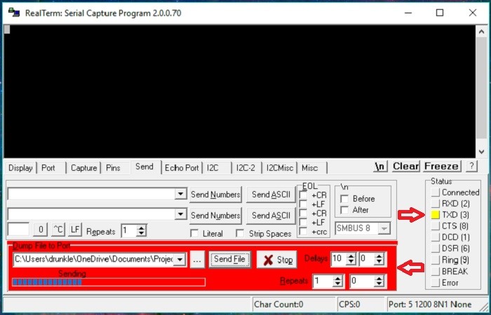
STEP 7 - Once the download begins, RealTerm will turn the "Dump File to
Port" dialog box red. As the file is sending data the TXD status
indicator should turn or blink. The progress bar grow should also get
growing.
|
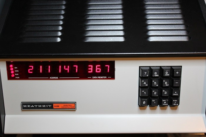
On the H8 end, the LED display will show the number of bytes received and the current data byte received all in Octal form.
|
The file transfer will continue until the last byte is send and the checksum is verified. Upon completion the H8 will give a short beep.
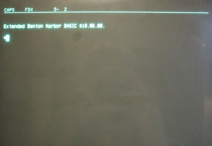
Since this example loads Extended Benton Harbor BASIC 10.6.0, a press on the space bar on your terminal device displays the welcome message.
This completed the sending of the file.
|
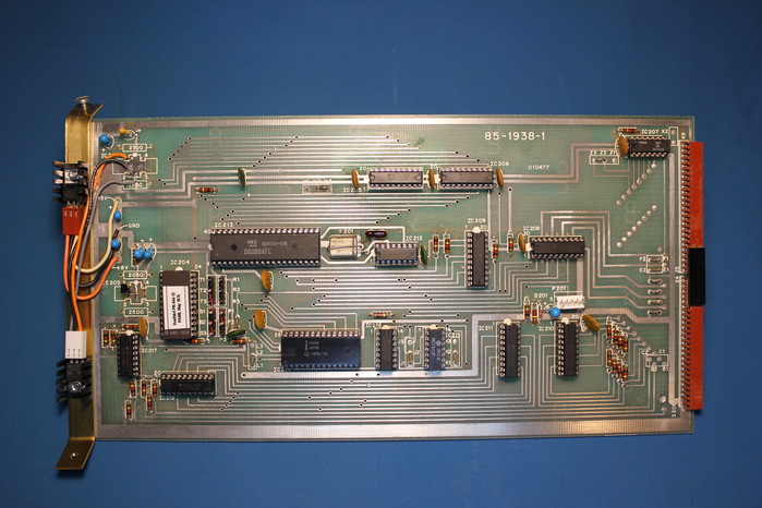
My original H8 system came with a working CPU card. While I was corresponding with other Heathkit computer enthusiasts at the SEBHC website and forum, I ran in to someone who was looking to reducing their inventory of H8 parts. In a generous offer he shipped me a H8 CPU, a H8 front panel and a few hard to find parts. Normally I try to collect enough parts to repair or replace most anything on all my restorations. So the hard to find parts received where gratefully added to my H8 spare parts inventory. Both PC boards where already in the process of being restored. The CPU board already had all the IC sockets and a few parts removed. I started my normal restoration process of evaluating the board, generating a list of areas of concern and finally an action item list. The CPU board was a good condition with only a few areas of foil damage that needed special attention. First both sides of the PC board where cleaned of any dirt, corrosion and old solder flux. Like many early boards shipped by Heathkit, the was solder mask was only on the back side of the CPU board. The 35+ years old solder masks was flaking away with age. Something I have seen all to often in my other restoration projects. All the IC sockets where replaced with high quality versions. Since I knew there where some solder connections to be made under several IC sockets on the top side of the board, the sockets selected had provisions to allow soldering on both sides of the board. Each completed soldered joint was electrically verified for proper continuity. Some modifications where need. The H8 CPU board used three voltage regulators. One for +5 volts, another for -5 volts and finally one for +12 volts. Unfortunately the +12 volt and -5 volt regulators original selected by Heathkit engineers are today next to impossible to fine. The readily available 79L05 (-5V) and 7812 (+12V) regulators where used. While I was at it I used a new 7805 (+5V) regulator. All three regulators can be seen on the left side of the CPU board in the supplied picture. Since the board did not come with an aluminum mounting bracket, I ended up fabricating one out of 1/2 x 1/16 inch brass stock. Yes I said brass. I did not have any aluminum stock in the size I needed. Given the updated voltage regulator section, my bracket design was quite simple. Two 6-32 tapped holed on each end to secure the board assembly in to the case, two 5/32 clearance holes to mount the PC board/voltage regulators to and two bends at each end to mach the Heathkit mounting system. Finally I power up the board without any ICs to verify the voltages. I then installed all new ICs, installed in to my H8 system case and powered it up. Everything worked the first time! I ran a 48 hour burn-in/ memory test for verify proper operations was indeed achieved.
|
 |
| Testing the second CPU board |
|
|
|
|